


محتويات
- How do two Device Communicate through UART?
- UART on ESP32 board:
- how to use it by code in default case?
- If using UART2, we will initialize it as follows:
- If using UART1, we will initialize it as follows:
- ESP32 to ESP32 Serial Communication
- important note:
- Master ESP32 Arduino Sketch:
- Slave ESP32 Arduino Sketch
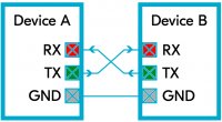
How do two Device Communicate through UART?
On one end the transmitting UART converts parallel data from a CPU into serial form then transmits the data in serial form to the second UART which will receive the serial data and convert it back into parallel data. This data can then be accessed from the receiving device.
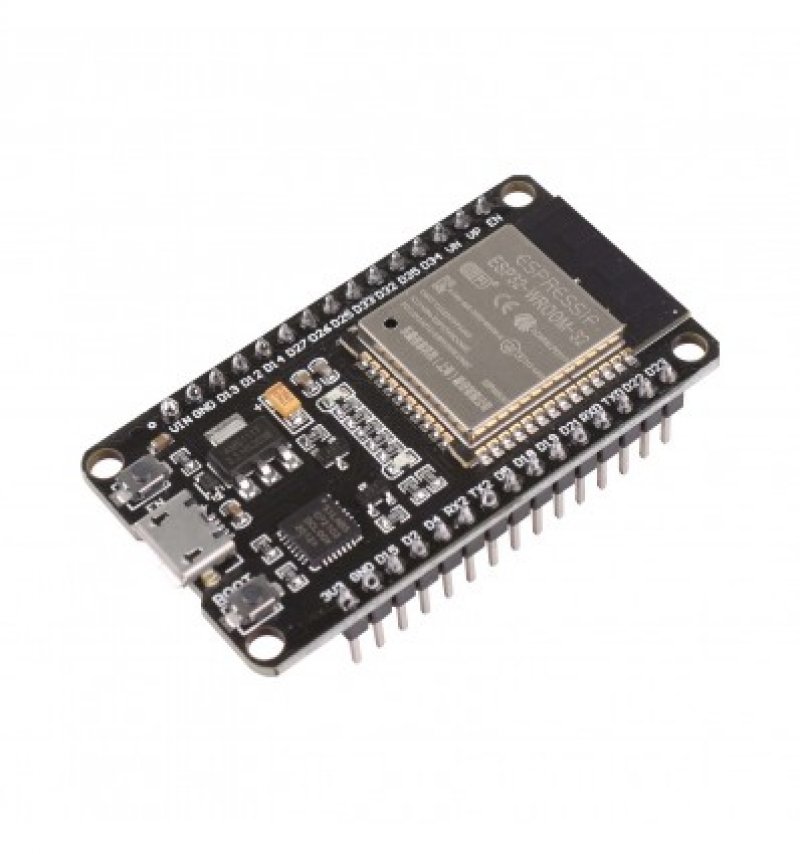
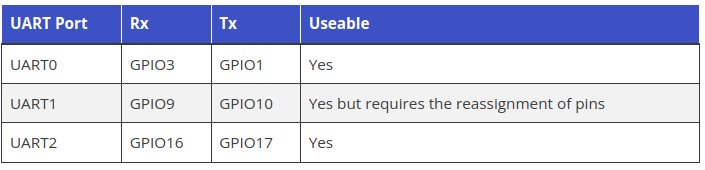
UART on ESP32 board:
By default, only UART0 and UART2 can be used. To use UART1, we have to redefine the pins because default pins of UART1 such as GPIO9 and GPIO10 are internally connected to the SPI flash memory. Also, on some ESP32 boards, they are even exposed on the pinout headers. Hence, we can not use UART1 directly without reassigning pins in Arduino IDE.
يمكن استخدام UART1 لكن يحتاج الى اعادة تعريف للمنافذ بدل من GPIO9 and GPIO10
how to use it by code in default case?
If using UART2, we will initialize it as follows:
If using UART1, we will initialize it as follows:
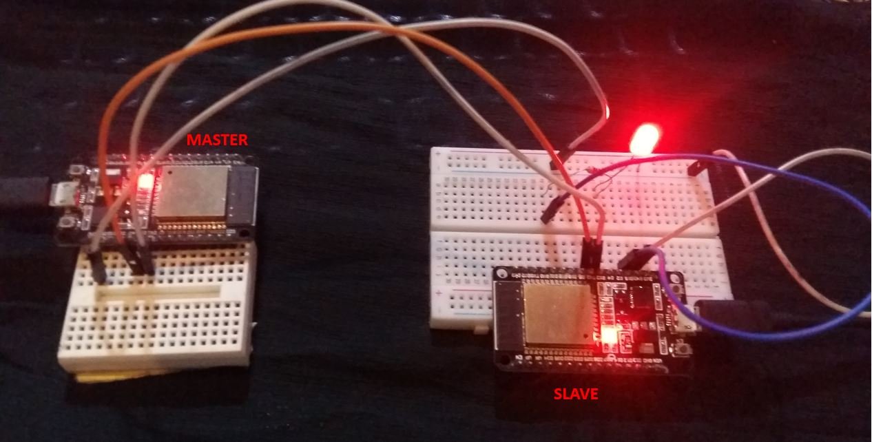
ESP32 to ESP32 Serial Communication
Let us see an example of serial communication where the ESP32 master will send either ‘1’ or ‘0’ to the ESP32 slave. The slave will then receive that data and control an LED connected with its digital pin. We will use UART2 to communicate between the two boards.
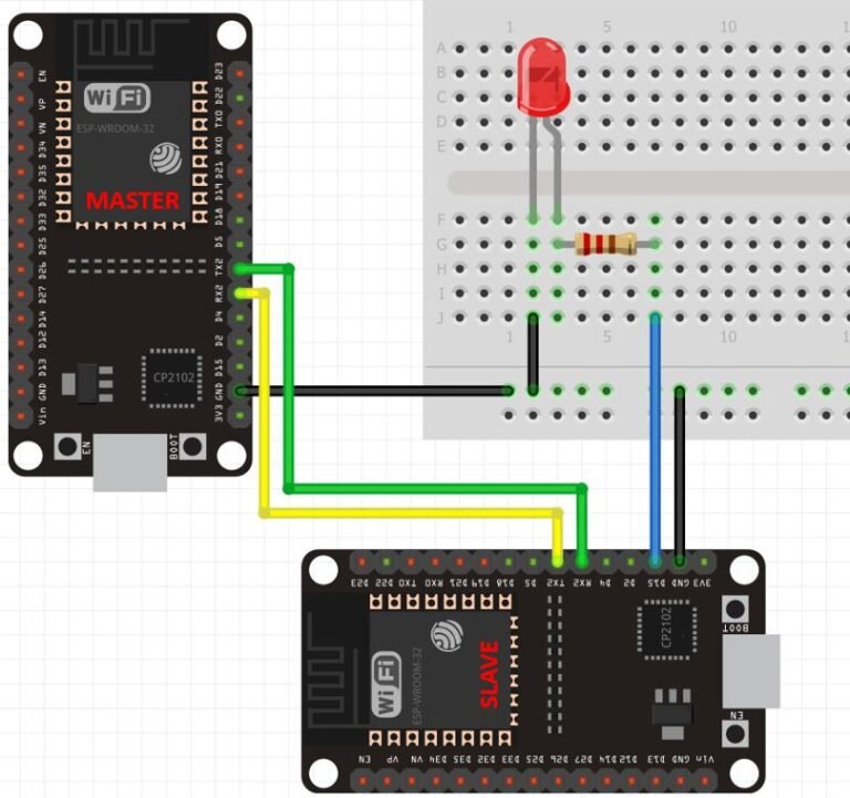
important note:
Connect TX2 pin of master ESP32 board with RX2 pin of slave ESP32 board. Likewise, connect RX2 pin of master ESP32 board with TX2 pin of slave ESP32 board. Also make sure both ESP32 boards have their grounds in common.